Deliver to UAE
IFor best experience Get the App


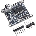
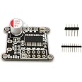
3pcs AS5600 Magnetic Encoder High Precision Sensor Module, 12bit, I2C, PWM, Voltage Output, Non-Contact, 23x23mm
Details
- BrandUMLIFE
- Model NameAS5600 Encoder
- Connectivity TechnologyI2C
- Included Componentsothers
- Operating SystemLinux

Description
🔧 Elevate Your Engineering Game!
- VALUE PACK - Get three sensors to supercharge your innovations.
- COMPACT DESIGN - Perfectly sized at 23x23mm to fit in any project.
- PRECISION REDEFINED - Experience 12-bit high accuracy for your projects.
- NON CONTACT TECHNOLOGY - Enjoy reliable performance without wear and tear.
- VERSATILE OUTPUT MODES - Choose between I2C, PWM, and voltage outputs for ultimate flexibility.
The AS5600 Magnetic Encoder Sensor Module by UMLIFE offers high precision angle measurement with a 12-bit resolution. This non-contact sensor features multiple output modes including I2C and PWM, all within a compact 23x23mm design. Ideal for various applications, this package includes three sensors to enhance your projects.
Specifications
| Brand | UMLIFE |
| Series | AS5600 Magnetic Encoder |
| Operating System | Linux |
| Item Weight | 0.176 ounces |
| Product Dimensions | 0.91 x 0.91 x 0.91 inches |
| Item Dimensions LxWxH | 0.91 x 0.91 x 0.91 inches |
| Color | 3PCS |
| Processor Brand | ARM |
| Number of Processors | 1 |
| Manufacturer | UMLIFE |
| ASIN | B094F8H591 |
| Country of Origin | China |
| Date First Available | May 8, 2021 |
Reviews
D**A
Works great
Works great, buttery smooth encoder, all boards worked, all items provided (magnets) can place magnet in a vertical or horizontal position.
A**N
Works out of the box using I2C on Arduino!
I saw there were some negative reviews or at least comments about it not working with PWM out of the box. Makes sense, and I'm glad one reviewer pointed out how to remove the R4 resistor to make that work.For me, I typically use the AS5600 magnetic encoder using the I2C protocol on Arduino, and so for my application(s) I wasn't interested in PWM. This worked out of the box without any modifications for me, and this ready-to-go board is a huge time saver instead of buying the individual AS5600 chip and soldering the pins to capacitors yourself.Here's how you do it:1) Connect Vcc to a power supply between 3.3V-3.6V or 4.5-5.5V, e.g. the 5V or 3.3V pin on your Arduino Uno. (if you look online for the AS5600 datasheet, you'll see it supports 3.3-3.6V and 4.5-5.5V, depending on how you connect the capacitors. However, this board has capacitors mounted in such a way that you can go either way! I tested it and it does work with both).2) Connect GND to the ground of your power supply (or Arduino Uno, for example)3) Connect the SCL pin to your Arduino's SCL pin, and the SDA pin to your Arduino's SDA pin. These are labeled on the Arduino Uno. On other boards, you'll need to look online for your board's pinout diagram to see which pins are for SCL and SDA.4) Download a library for the AS5600. A good one is: google "as5600 arduino seeeduino", you'll find a result on the seeedstudio Wiki page for a Grove 12 bit magnetic rotary position sensor (AS5600). On that page is a link to "Download the AS5600 library from github"Download and install that library to your computer, and run the "readAngle" example by opening up your Arduino IDE and clicking File->Examples->Seeed Arduino-Master->readAngle.You should be able to bring a magnet (such as the one included in the package) close to the sensor and using the Serial monitor, you'll see the angle change as you rotate the magnet.Hope this helps anyone else out thee.
T**Z
DO NOT USE 5 Volts VCC or MICROS that are 5Volts output
DO NOT USE 5Volts on these devices. They will stop working after a few minutes. Use Only 3.3 Volts and for Micros that are 5volts you will need to use a level shifter for the SDA SCL or any Digital Pins on the device./
D**S
Works Well I2C at 5V
I used a basic proven sketch to test hardware functionality. The one I used can be found searching "cybertice" in google.Overview of the setup required.- For people just tinkering. The tiny board but that has it's benefits for your builds. If you have high heat on your soldering iron try to control it the best you can on the low end for your solders temp specification. Use LED based solder for better control from my experience with these.- I2C setup right out of the bag, don't change anything if you want the best resolution at 5v. If you need analog take the R4 resistor out. about that in the manual.- To test hardware functionality before attempting to code; try searching "cybertice". There was a great instructional/source code there on their page and githubs without the use of an LCD screen.- Pinout as follows:* Pin (2) for DIR (default in the cybertice library)* Pin SDA and SCL to the Arduino* 5v and GND- After you download their library run the example "readAngle" and approach the magnet within the 0.5mm-3mm spec works greatI will purchase more of these now. 5pcs it is. (Lots of 3d prints available for these already, just search for them)
C**S
Works as expected, with one modification
I had to remove the R1 and R4 resistors and use 5vdc input to get the described analog output on out pin. I2C still works fine with the resistors removed. It may be that only one of R1 or R4 needs to be removed, but I didn't try that. With that change I was able to see a very consistent 0-5 vdc change that corresponded to 0-360 degree rotation. 90 degrees was 1.25 vdc, and 180 degrees was 2.5vdc, and 270 degrees was 3.75 vdc. right at 0/360 degrees, the voltage changed from 0 to 5 vdc. Now very happy.
S**S
Good product---Mind the configuration!
These work great, but they are wired for I2C ONLY! If you are looking for analog output, you will need to REMOVE the resistor which is connected to the PG0 pin (pin #8). then you will get an analog voltage output, at the out pin on the board. Without this, the output voltage will always be at Vcc (3.3 or 5V). Hope this helps someone....otherwise, they work great!
Common Questions
Trustpilot
1 month ago
2 months ago
Get the App
